Projects
More detailed description of projects saved in github.
Project maintained by rickwelch Hosted on GitHub Pages — Theme by mattgraham
Arduino JSON service provider Example Project.
- Description of project
- simple project with 4 digitial inputs and 4 outputs
- currently in use for hydroponic tomatoes
- photos here 6/23/22
- Hardware Description
- Clone and setup
- How the UI works
Project Description
This project started as a simple example project but became an actual project in use. I finally started to have some success with hydroponic tomatoes and were going away for 2 weeks. I added float switches on the tomato buckets and set up a 5 gallon tank to supply nutrients when the root tanks are low. I’m currently only using three of the four switches and pumps.
This project has four digitial inputs and four digital outputs. The inputs are connected to float switches that will pull the inputs to ground if the liquid in the tank is above the float switch. The four outputs are connected to a relay board to control either pumps or flow switches to fill the tanks.
On the surface it would seem this could be done within the Arduino itself but there can be many reasons for yealing control to a central controller like restricting fill times or measuring filling times to get a measure of usage.
Parts:
1 Arduino WiFi or 1 Arduino Uno plus an Ethernet Shield (Projects for each will be linked as soon as they are tested)
4 Float Switchs,
1 Prototype Shield,
1 Relay Board,
3 Submersible Pumps
Schematic:
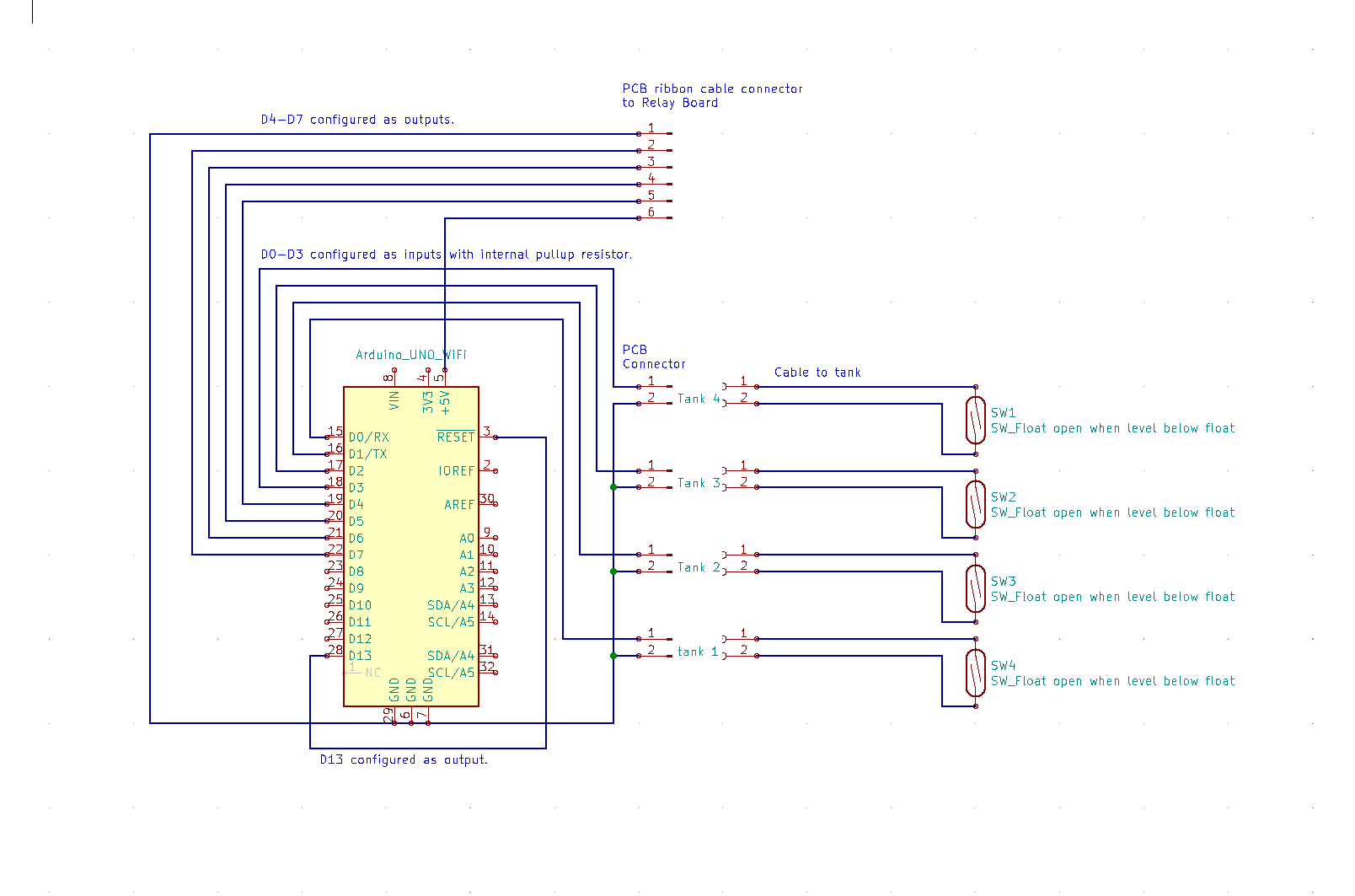
Installation and modification
The sofware for this project is in the Arduino HTTP Service Provider Uno WiFi repostitory. A similar project for the Arduino Uno with an Eithernet shield is forthcoming.
All customization can be done in the ~/include and ~/lib folders. See the REAMD.md files in those folders.
Device drivers live in ~/lib. The Device, DigitalIn, and DigitalOut drivers were copied direclty from the Arduino Drivers library. The Pump driver was copied directly from DigitalOut, it was renamed, the name was changed to Pump in the init() method and the HIGH / LOW abstractions were set in the .h file. See the README in that folder for more information on these drivers and how to create your own drivers.
The ~/include folder has three files, wifi_secrets that you must update with your WiFi information. Compiling and uploading the code beyond that should produce the project described above which you can then test with a protoboard before doing any custom modification.
Using The Controller
Once compiled and uploaded to the Arduino, direct a web browser to the IP address specified in local_include.h. You should be returned the following
{"Controller":"Example Project","RSSI":"-64 dBm","free_ram":"5203","Tank_0":"LOW","Tank_1":"LOW","Tank_2":"LOW","Tank_3":"Low","Pump_4":"OFF","Pump_5":"OFF","Pump_6":"OFF","Pump_7":"OFF"}
Where Controller is the controller name set in local_include.h, RSSI is the WiFi signal strength, free_ram is the amount of RAM unused on the Arduino and Pump_0 through Pump_3 are the current state of input pins D0 through D3. In the above example, either the cables are not plugged in or all the tanks are below float level. You can connect pins 0-4 to ground and rerun the query to see the dfferent results.
To change the output value of pin D4 to LOW or to turn the pump on, on the browser issue the command: your-ip-address/command/Pump_4/ON to set pin D4 to ON state (LOW). You should be returned:
{"Controller":"Example Project","RSSI":"-64 dBm","free_ram":"5203","Command Status": "Pump_4 switched to ON", "Tank_0":"LOW","Tank_1":"LOW","Taml_2":"LOW","Tank_3":"1","Pump_4":"ON","Pump_5":"OFF","Pump_6":"OFF","Pump_7":"OFF"}
And pin D4 will be set low.